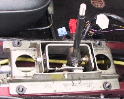
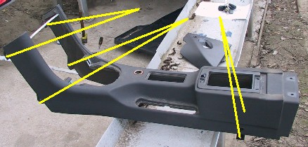
The original setup
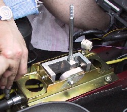
The new setup with the Mike Satur part
M O D I F I C A T I O N S : TUNING, Slick Shift Kit
After reading many good comments and a positive experience with David's SSK-equiped MGF, I decided to go for the Mike Satur Slick Shift Kit (SSK). It's a slightly modified MkII of the famous Slick Shift Kit, as when ordering the kit, a new batch of kits went into production.
Although fitting looks like a job for the more experienced DIY enthusiast, I decided to have a go with it... and I must admit, I was a bit lucky that my brother in law had a look at it when passing by. He's more confident with such mechanic stuff than I am, so he perfectly knew what he could do and what you better don't do.
|
The original setup
|
The new setup with the Mike Satur part
|
The SSK comes in three parts:
- the gear selector part, as shown in the picture above
- the endpoint for the cables (will be located at the bottom, rear of the car)
- a new clip (MG Rover part: UYC10006)
M i k e S a t u r S S K I n s t a l l a t i o n --- p a r t o n e
When removing the original part and eventually installing the new gear selector a rather huge amount of trim needs to be removed to gain fully access to the part.
IMPORTANT:
disconnect the negative wire from the battery (SRS is involved you do not
want to wake up this system)
 |
Start
with removing the central console - remove the central, top air vent by slightly pulling it up and out of its position. Eventually use a flat head screwdriver. - remove the radio (with the tools that came with the head unit) or by pushing the unit from inside the dashboard (the opening from step 1 is ideal for this). - remove the gear knob (probably screwed on, but some models are fastened with small screws) - remove the fascia of the central console by slighly lifting it at the bottom. Five clips are holding this piece of plastic in its place, two at each side of the switch panel, two at each side of head unit's location and one at the top. The clips are quite strong, and rather difficult to manipulate from behind. Give it a try by pulling and some pushing from behind. - disconnect the cables and plug from clock and oil temperature gauge - disconnect the plugs from the switch panel (it's good to write down which plug was connected on which location... it makes refitting a lot easier) - the switch panel can be removed from the fascia... it will make refitting a lot easier - again). |
After removing a part of
the central console, it's time to remove the rest of the transmission tunnel.
- Losen the T-bar behind the seats by using a Philips head screwdriver on the
three tonneau fixing things. Give it a strong pull in the direction of the seats
to release the clips. They are quite strong, and the male part (red) will come
lose from the T-bar but will keep stuck in the female part (white).Use a tool
(flat head screwdriver or a set of pliers) to seperate them and to relocate
the male plug on the T-bar (for later refitting). Relocate the T-bar, i.e. on
top of the hood which is fold down.
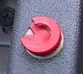
female and male plug
normally holding the T-bar in its place.
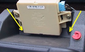
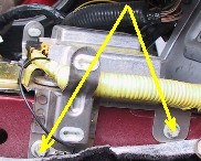
- Remove the light blue plug from the sensor of the volumetric alarm (light brown, white box) and unscrew both screws as shown in the picture below (yellow arrows).
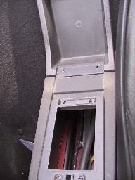
- Open the box under the
arm rest and remove the plastic container by pulling the front of the box in
upwards direction and slightly to the front of the car. This action results
in a new set of screws becoming visible... remove them.
- Open the drop down bin and remove the two screw at the base of the lid. You're
now able to remove both lids as one piece and you're able to remove the drop
down bin as well.
- Remove the ashtray and
unplug the cigarette lighter.
- Remove the handbrake gaiter starting at the front and slide it in that direction
to clear the rear clip. Use some gentle force to slide the handbrake grip from
the steel handbrake.
- Remove the triangular 'plastic item with interior light' in the footwell by
removing two screws: one at the base and the other one near the light. Repeat
this in the other footwell.
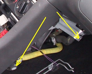
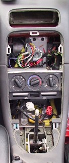
- At last, remove the six screws, responsible for keeping the transmission tunnel in its place. See picture below for the location of those screws.
- If you haven't disconnected
the battery yet, do it now and leave the car in this condition for more than
10 minutes before continuing with the next step.
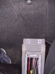
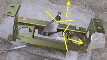
- The SRS unit needs to be relocated to gain access to a bolt that is securing
the gear selector in its place (together with two other bolts and four nuts).
The picture below shows two of the four torq bolts located at one site of the
tunnel.
- A nut and bolt combination
at the rear of the selector unit attaches the pipes with gear linkages to the
unit. Remove it and mark the pipes.
- Remove the bolts and nuts keeping the selector unit in its place.
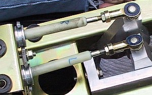
- Turn it upside down and unclip the joint linkages (it is possible, so don't
be afraid to use some force) and unscrew the part of the joint which is still
attached to the cable but will be replaced by new ones. Unscrew the new joints
from the new gear selector unit (see picture below) and attach them to the cables
while mounting the pipes on the new selector unit. Once pipes, cables and joints
are attached again, screw the other end of the joints back in the selector unit
(have a look at the other picture below).
- Now you're able to install/refit everything in reverse order . . .item.
M i k e S a t u r S S K I n s t a l l a t i o n --- p a r t t w o
- Get the
rear of the car up and secure its position so it is safe to work under the car
and to use some force on certain parts of the car.
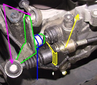
- Get under the car and remove the clip (a new one is added to the MS SSK) and
you are able to relocate the cable, on the picture shown as yellow. Use some
force to 'break' the joints (pink/purple on the picture). Remove the circular
clip and use a hammer to remove the pin (all blue) out of the green device.
(I hope this all makes some sense).
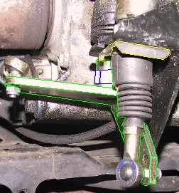
- Install the new device, joints, pin, ring clip and clip and you will end up with the following (picture taken from another angle, same colors):
M i k e S a t u r S S K I n s t a l l a t i o n --- p a r t t h r e e
Adjusting and calibration of the setup.
update (Oct 1st 2003): An Mk3 version of the SSK has been developed. It is still available for the F and TF. Same price as before: £175.00
update
(Summer 2004): An Mk4 version of the SSK has been developed. The
following can be found at Mike Satur's website:
" The new SSK IV is manufactured in-house on our own jigs and fixtures
to ensure accurate and precision assembly and now with revised components to
give an improved gear change. Some components have be en upgraded for competition
use and will withstand even the roughest of use.We have made the gear lever
out of brushed stainless steel to improve the looks and strength, this could
be polished for a chrome effect. The new SSK 1V comes with a unconditional parts
replacement warranty if fitted at our workshops.
The SSK IV comprises a complete replacement gear lever assembly and a gearbox
bell crank assembly with 4 new sealed rose joints for the cable ends. Spare
rose joints are £7.50 each and can be bought separately for spares although
this part has been tested for a 1,000,000 cycle life without showing any significant
signs of wear or breakage. Although we have not had a price increase for this
part since it was first developed due to raw material price increases and improved
parts specifications we have had to increase the price to £195.00 plus
VAT (£229.12) We feel this still represents excellent value for money when compared
to similar products on the market. "