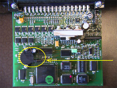
MAP sensor on the EFI circuit board
and how the vacuum hose wil fot on to it
E N G I N E S : PTP RT-Sport 165 kit
Fitting
instructions: as provided by PTP Ltd.
1. Refer to service manual for car concerned, and remove cylinder head
2. Remove the old cylinder head and plastic inlet manifold assembly and retain
the following components for re-use from the manifold:
- Air Inlet Temperature sensor
- Metal fuel return pipe and injectors
- Idle air control stepper motor
- Throttle body and berather pipes
3. Remove from the old cylinder head the following components for re-use:
- HT leads, distributor cap, rotor arm and anti-flash shield
- Water outlet elbow
4. Assemble the new inlet manifold
- Fit the new upper inlet manifold (plenum) to the manifold with gasket and
screws
- Fit the throttle body assembly to the plenum
- Fit the air inlet temperature
sensor with its new afaptor into no.4 branch of the new lower manifold
- Fit the Metal fuel return pipe and injectors into the lower inlet manifold
- Carefully manipulate the metal fuel return pipe as to align both support bolt
fixings on the underside of the new inlet manifold
- Fit the Idle air control stepper motor with the new self-tapping screws provided.
5. Assemble the new cylinder head:
- Fit the cam belt top cover and camshaft pulleys
- Fit the two new inlet manifold studs into the top two fixings holes in the
head
- Fit the five new exhaust manifold studs
- Fit the distributors cap and leads
- Fit the new cam belt tensioner
- Fit the water outlet elbow and gasket
- Fit the new inlet manifold assembly
6. Fit the new cylinder head assembly as detailed in the service manual using
the new cam belt. Pay attention to the cranksaft and cam positioning to avoid
piston/valve foul.
7. Fit the new manifold support strut to the manifold and cylinder block using
the new bolts supplied.
8. Connect the fuel pressure regulator valve sending hose to the right hand
end of the intake plenum.
9. Fit the exhaust manifold.
10. With camshaft
coverremoved, pour oil over the camshaft and valve gear to ensure adequate lubrication
on start up. Fit cam cover.
11. Fill the engine with good quality mineral (not synthetic) oil meeting the
viscosity requirements of the standard engine and change the oil and filter
after the running in period of 1,000 miles. Part or fully synthetic oil may
be used to advantage after running in.
12. For normal road use, the standard schedule may be used. If frequently used
on circuit track days
, it is recommended to reduce the change interval for oil and filter to 3,000
miles.
13. Position the ECU safely and securily (ties not supplied)
Connect interface link connecting lead to ECU and Engine harness
Solder connect single black wire to permanent 12 volt live (Not Starter Motor)
Connect the ECU MAP hose to the fuel pressure regulator valve sending hose via
the T-piece supplied. *
14. After fitment of kit
- Turn ignition on (fo not fire up) and depress throttle to fully open 3 times.
- Switch ignition off
- Switch ignition on, start engine
15. If tick-over wonders, repeat 14
16. If the vehicle has stalling issues, try to open the throttle stop in 1/4
turn intervals (so that the butterfly opens more) and then repeating step 14
(trying the vehicle at each interval), this should cure it, unless there is
a fitting error.
*
Additional instructions
Don't know where PTP
Ltd. is getting it from, but the 1.8 MPi engine has on the original setup a
vacuum hose from inlet manifold to ECU (the location where the MAP sensor is
positioned). The new setup, with the new EFI ECU and new manifold is np different
to the standard setup. There's no need to cut the 'fuel pressure regulator valve
sending hose' and fit the T-piece as the manifold has a second outlet for a
vacuum hose. Just connect the original vacuum hose to the manifold (right hand
side) and the MAP sensor inside the EFI-box.
MAP sensor on the EFI circuit board
and how the vacuum hose wil fot on to it
I received the additional instructions after a complaint that the car was running very unstable and that it doesn't wanted to start anymore after several tries. Service of PTP Ltd. was gerat as the replied within an hour with a e-mail containing a how-to and a set of 4 pictures how to ttach the vacuum hose.